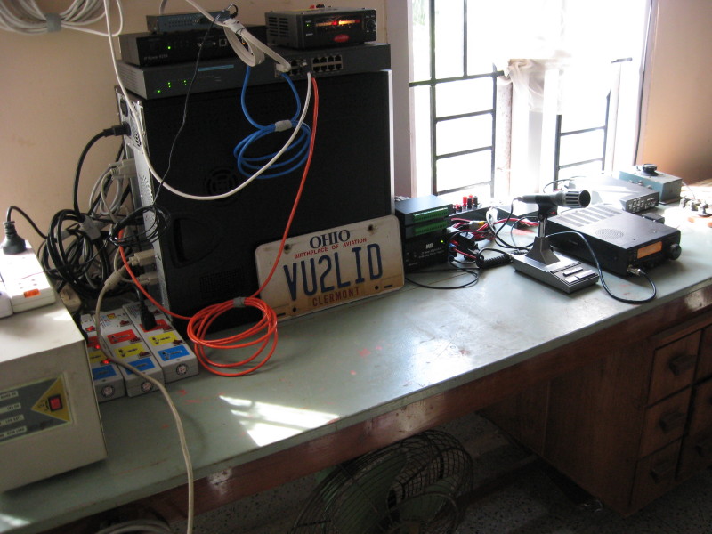
It became clear by 2007 that it will be very difficult/impossible to have even a simple dipole, to operate from my N8LI QTH. We had reliable high speed Internet connection at both locations, VU2LID and N8LI. I thought that it will be much better to operate VU2LID remotely through an Internet link than to operate N8LI with inefficient shortened antennas erected inside the house.

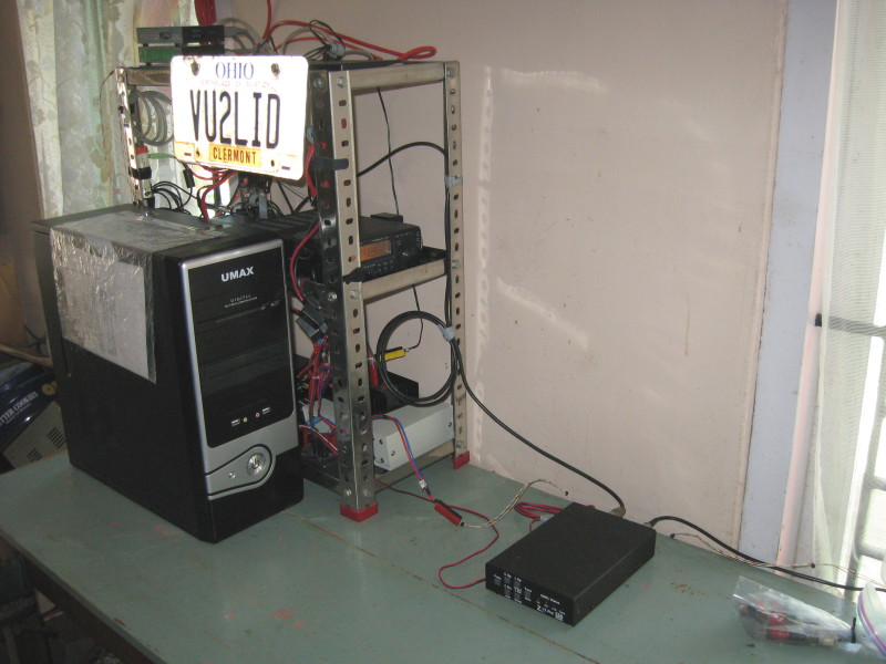
Please don't be confused by the Ohio license plate 'VU2LID' :) The station in the above picture is located in India. Please check the album for more pictures.
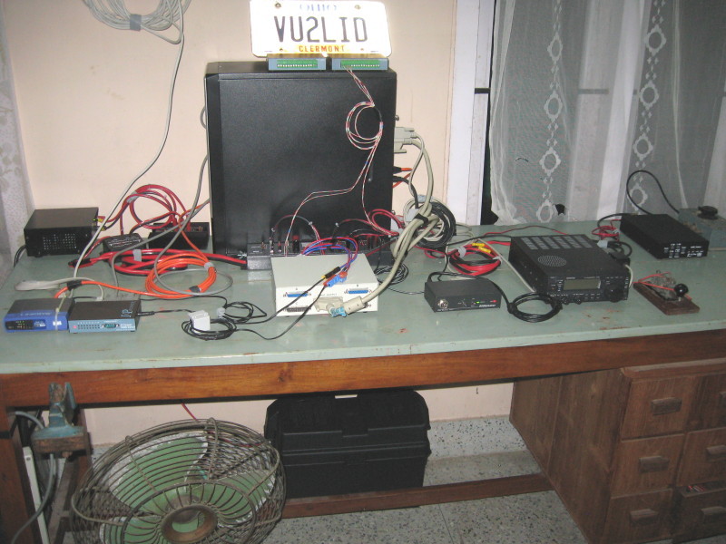
Version 0.0 was not capable of transmitting. It was receive only, since I could not find time to test and activate the remote PTT control. Receiving also broke down after a month (later in 2008 December I found that the control computer SMPS had failed).
Version 1.0 of the remote setup was planned, taking into account lessons learned from the failure of Version 0.0. The system is much simpler (compared to Version 0.0). All the devices (including the computer) are powered from 13.8VDC, with automatic switchover to battery, during mains (230VAC) power failure. The system now uses a specially assembled computer with very low power consumption (around 23W), running Debian GNU Linux. Please check the album for more pictures.
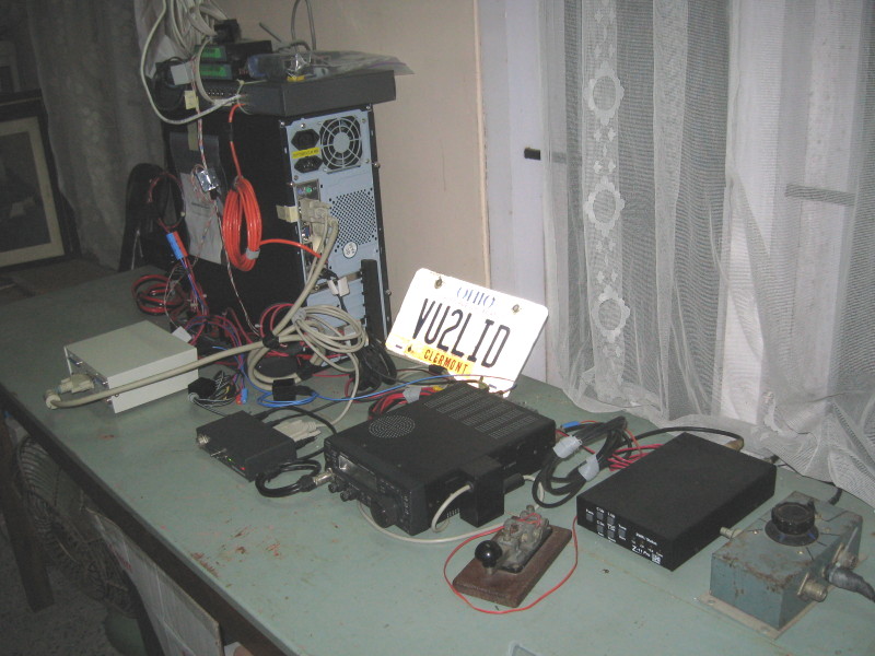
A Linksys network switch used in Version 1.0 was generating strong RFI on several bands. It was replaced with another modified switch with better RF shielding. CW keying through a parallel port interface using 'cwdaemon' was also made operational. Now the remote station is capable of operating on CW by keying the rig directly through straight key jack !
An 8GB microdrive in Version 1.0, used as the second HDD of the control computer, used to fail after a few days of uptime. That microdrive was replaced with a 32GB solid state drive. This change is expected to increase uptime of the control computer significantly. Please check the album for more pictures.
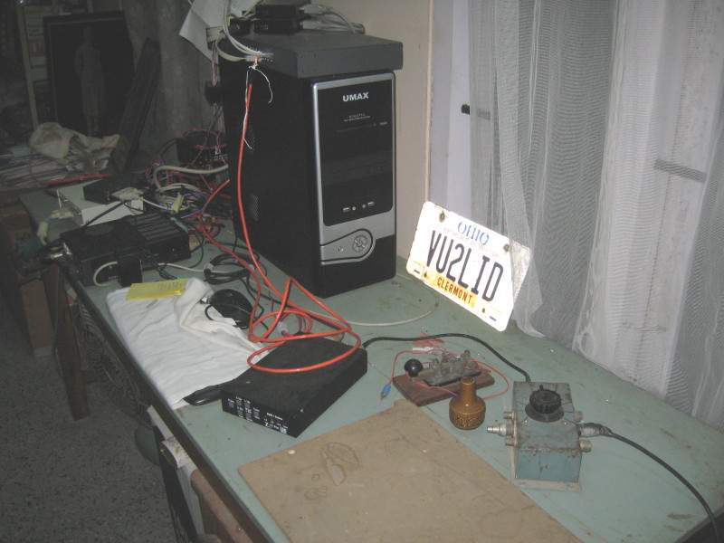
The solid state drive used as the main drive for Version 1.5 was a compact flash card with a CF-IDE adapter. This was probably a bad choice - the drive failed approximately after 7 months. In addition to this the VIA-PC1 motherboard was also giving intermittent problems. The station control computer completely broke down by March 2010, making the station inacessible. The Cat5 Ethernet cable connectors used started developing frequent problems, since the locking tabs of the connectors had broken off.
Thanks to VU2JN Professor, VU2SXA Sunu, VU2TER Roy and other friends who made numerous attempts to identify and fix the problems ! Sunu finally replaced the Motherboard with a new Intel Atom motherboard, replaced the boot drive with a conventional SATA drive and installed Debian GNU/Linux in the new system. Later after measuring the total power consumption of the new station control computer, to my surprise found that it is comparable (approximately 25W) to that of the old VIA-PC1 based system (approximately 20W).
Please check the album for more pictures.
In October 2010 a version of DD-WRT being used in the Internet Router was compromised and the remote connection to the home network completely broke down. In addition to this, a poorly setup Sealed Lead Acid battery back up power supply and charger for the Internet Router and DSL modem brokedown a number of times. The remote station broke down completely and was not operational for more than a month.
In November 2010 a more reliable battery backup system and powersupply was installed for the DSL Modem and Router. The present syetm is setup to recover automatically under various common error conditions like extended power interruptions.
A new antenna system (a horizontal loop) was installed, in addition to the existing multiband GP antenna.
The old bulky network switch was replaced with a power efficient D-Link switch. The new switch also generates much less RFI. Other changes include provision to remotely select one of the two antennas using a coaxial switch. The Parallel Port connected CW Daemon keying was replaced with Serial Port based keying, using a USB-Serial Port adapter. Rig control was also moved to a Serial Port connected to a USB-Serial Port adapter. Please check the album for more pictures.